

Features
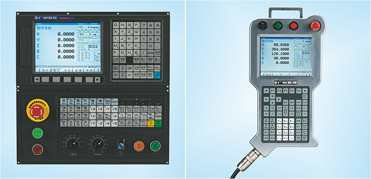
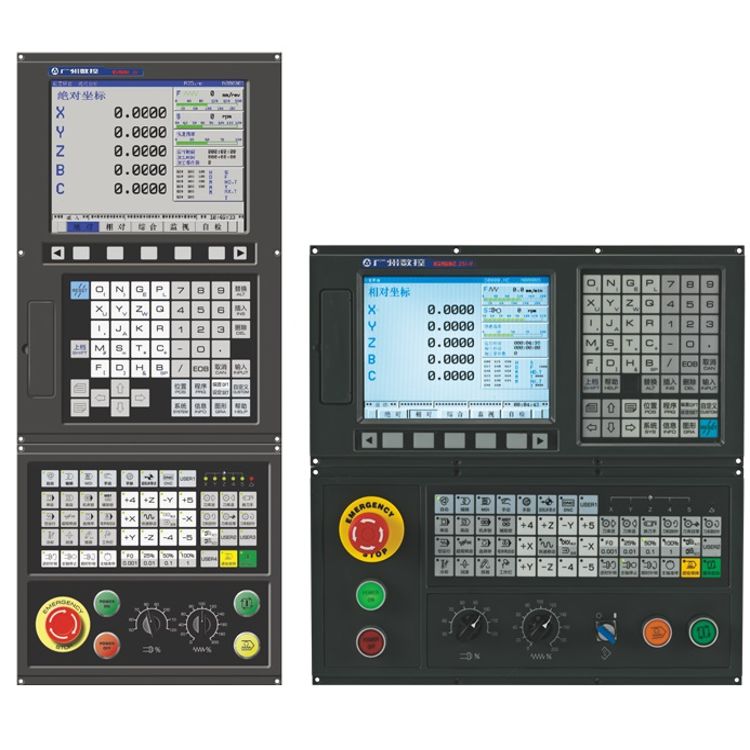
1. GSK25i is a high-performance CNC system characterized by its powerful functions and simple operation. It is applicable to the multi-function machining centers, boring machines, milling machines and drilling machines with 3~5 axis linkage.
2. GSK25i adopts a high-performance hardware platform and Linux operation system. It supports up to 8 axes with 5-axis linkage, and provides five-axis control functions, such as five-axis RTCP (tool center point control), inclined plane (3+2 positioning) machining and five-axis manual feeding. In addition, it supports the feed axis synchronization and PLC axis control as well.
3. The system employs GSK-Link industrial Ethernet bus and servo real-time communication. When matched with GH series servo unit (high speed and high precision) and servo motor with a high-resolution absolute encoder, it can realize a positional precision of 0.1|m; with the adoption of PID position closed loop, and featured by its advanced preview ability (preview up to 2000 blocks), path smoothing ability and 1ms interpolation cycle, the system realizes high-speed and high-precision machining for small line section as well as the machining for mold parts.
4. Open PLC; support for PLC online editing, diagnosis, signal tracking functions; I/O points can be extended to 1024/1024 at most, thus satisfying the control of large-scale and complicated devices.
5. GSK25i realizes DNC machining and data transmission through USB interface and network interface based on TCP/IP. By using the upper PC software, it realizes remote monitoring, remote diagnosis and remote maintenance, network, DNC function and three-dimension simulation running by G code.
Function Parameters
Advanced hardware

1.High-performance and high-configuration
hardware platform, which satisfies the demands for complicated operation and
machining, such as five-axis linkage and high-speed and high-precision
machining.
2.GSK-Link real-time industrial Ethernet bus control, integrated cabinet,
high-resolution LCD, small size and simple connection.
3.Aluminum alloy front panel, stainless steel rear panel, firm and durable.
Five-axis machining function 8 controlled axes with 6-axis linkage
1.8 controlled axes with 6-axis linkage
2.Applicable to five-axis machines with worktable swinging, tool swinging or
both.
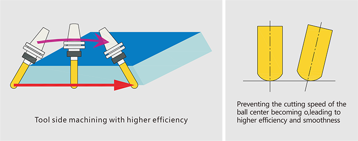
3.Five-axis RTCP (tool center point control)
4.Inclined plane machining (3+2) positioning
5.Five-axis manual feed
High-speed and high-precision machining

1.Advanced preview control (up to 1000
blocks), linear acceleration/deceleration before interpolation, S
acceleration/deceleration before interpolation
2.Jerk control
3.NUBRS interpolation
4.Multiple on-line path smoothing modes, coordinating the work efficiency and
surface quality in different types of machining.
5.G05 P1 Broken line transition mode
6.G05 P2 Bezier smoothing mode
7.G05 P3 B spline smoothing mode
High-performance servo system
1.High dynamic response servo motor,
current loop cycle as short as 100|s
2.Servo parameter dynamic self-adjustment
3.Servo motor equipped with a 17-bit (131072 lines) high-resolution absolute
encoder, which improves the machining precision and surface quality to a new
level.
4.Absolute encoder. No need to return to the zero point each time the system is
started up.
5.Large-capacity memory, 240M standard configuration, which can be extended to
500M.
6.Operations for program editing: New, Modify, Copy, Cut, Paste, Search,
Replace.
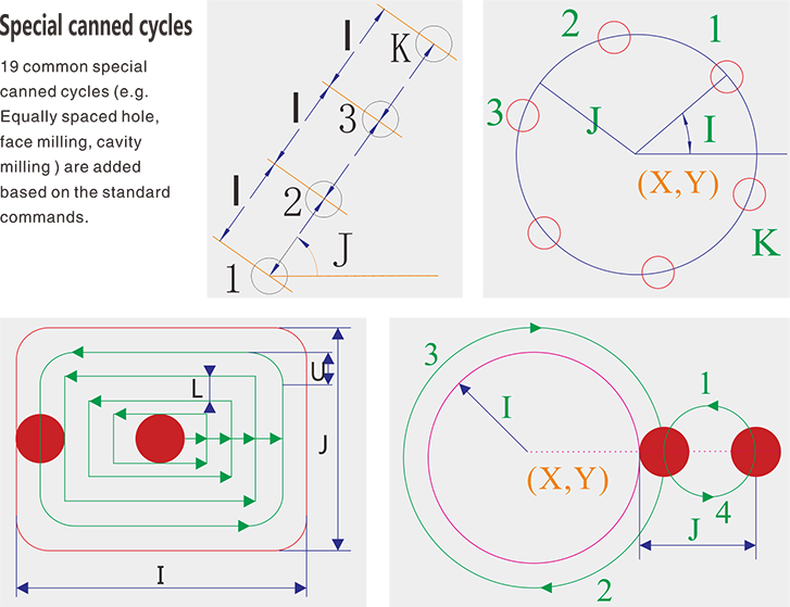
7.Plenty of macro commands and canned cycles, convenient for effectively
completing complicated machining.
8.Data transmission through U disc and network, DNC.
9.Simple debugging and maintenance, detailed alarm and diagnosis message.
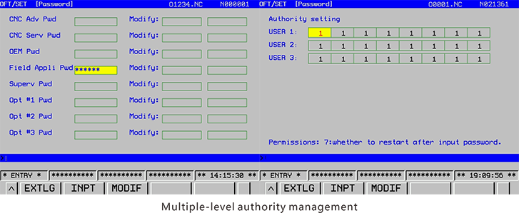
10.Multi-level authority management.
11.User-defined interfaces for secondary development.
PLC function
1.Ladder diagram programming.
2.Basic command process time: 0.5|s/step, program capacity: 12000 steps.
3.10 basic commands, 49 function commands.
4.Open PLC, PLC program can be modified and edited on the system.
5.Multiple PLC program select storage, run program selectable.
6.PLC axis control function.
Instruction List
|
No. |
Designation |
Specification |
|||
|
Axis control function |
|||||
|
1 |
Controlled axes |
Up to 8 controlled axes plus 1 servo
spindle |
|||
|
2 |
Linkage axes |
3-axis linkage |
|||
|
4-axis linkage |
|||||
|
5-axis linkage |
|||||
|
3 |
PLC axis control controlled axes |
Up to 4 axes |
|||
|
4 |
Feed axis synchronous control |
Up to 4 groups |
|||
|
5 |
Position detection device |
Pulse encoder (absolute), grating
ruler (absolute) |
|||
|
6 |
Least command increment |
Least command increment IS-B |
0.001mm |
0.0001inch |
0.001° |
|
Least command increment IS-C |
0.0001mm |
0.00001 inch |
0.0001° |
||
|
7 |
Min. detection unit |
Least command increment IS-B |
0.001mm |
0.0001inch |
0.001° |
|
Least command increment IS-C |
0.0001mm |
0.00001 inch |
0.0001° |
||
|
8 |
Max. command value |
±999999.9999mm ±99999.9999inch ±999999.9999° |
|||
|
9 |
Max. feedrate |
Maximum feedrate: 200m/min |
|||
|
10 |
Automatic acceleration/deceleration |
Linear, S curve
acceleration/deceleration before interpolation, jerk control |
|||
|
11 |
High-speed and high-precision
machining |
G05 advanced preview of high-speed
small line section, path smoothing, up to 1000 blocks can be previewed and
pre-read. |
|||
|
Five-axis control function |
|||||
|
1 |
RTCP function |
Tool center point control G43.4 |
|||
|
2 |
Inclined plane machining |
Five-axis positioning (3+2) machining
G68.2 |
|||
|
3 |
Five-axis manual feeding |
Manual feed in tool axial direction,
tool axis right-angle direction, or tool center point rotation direction |
|||
|
Programming function |
|||
|
1 |
Program format |
ISO command standard, program name: 0
+ 4 digits,Block number: N + 5 digits; |
|
|
G+ 3 digits; coordinate value IpY6
digits before decimal and 4 digits behind decimal, S +5 digits, M + 3 digits,
F + 6 digits before decimal and four digits behind decimal |
|||
|
2 |
Interpolation function |
Positioning, linear interpolation,
circular interpolation, helical interpolation, cylindrical interpolation,
polar coordinate, spline curve interpolation. |
|
|
3 |
Workpiece coordinate system |
Basic coordinate systems: G52YG59;
additional extensive coordinate systems JG54.1J: 48 groups |
|
|
4 |
Tool compensation |
C tool compensation function, 400
groups of tool compensation |
|
|
5 |
Programming function |
More than 100 G commands in total,
including 12 types of common canned cycle, 19 type of special canned cycle
and compound cycle, face milling, coordinate system rotation, scaling, mirror
image, automatic measurement of tool length, tool center point control,
inclined plane machining command, four nesting levels of subprogram call, B
type user macro program. |
|
|
6 |
Program storage |
Program storage capacity: 240M, which
can be extended to 500M. Number of programs storable:400 |
|
|
7 |
Reference point function |
G27 Reference position return check;
G28 Reference position return G29 Return from reference position; G30 2nd,
3rd, 4th reference point return |
|
|
8 |
Skip function |
G31 Skip function, used for measuring
tool and workpiece |
|
|
9 |
Programmable control function |
Programmable stroke limit (G22, G23),
programmable data input (G10) |
|
|
Operation function and display
function |
|||
|
1 |
Operation mode select |
AUTO, MDI,EDIT, MANUAL,MPG,ZERO RETURN, DNC |
|
|
2 |
ON/OFF operation |
Single block, block skip, machine
lock, auxiliary function lock, optional stop, dry run, restart, emergency
stop, overtravel release, cycle start, feed hold, manual continuous feed,
step, rapid traverse, MPG, spindle override, feedrate override, rapid
traverse override |
|
|
3 |
Setting |
Tool length compensation measurement
input, workpiece offset measurement input, parameter setting help, servo
parameter setting. |
|
|
4 |
Program operation |
New, edit, delete, rename, search,
copy, paste, read, transmission,background editing, dynamic graph
simulation |
|
|
5 |
Help function |
Alarm message explanation, operation
description, parameter description, macro command description, G command
description, PLC address description, counter |
|
|
6 |
Display |
10.4 inch LCD with resolution of
800Y600, or 8.4 inch LCD with resolution of 640Y 480, Chinese/English
display, dynamic graph, clock, process time, run time, part count, modal
information, actual speed, hardware/software version, ladder diagram, alarm
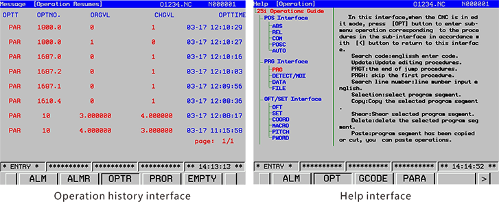
message, diagnosis message, alarm history, operation history. |
|
|
Operation function and display
function |
|||
|
1 |
M function |
M code with 3 bits, multiple M code
command, M code for calling macro command or subprogram |
|
|
2 |
T function |
T code with three bits, tool life
management |
|
|
3 |
S function |
Y10V analog voltage output from analog
spindle interface, digital spindle, S code with five bits, spindle speed
setting, multiple spindle control, spindle orientation, M type and T type
gear shift, floating taping, rigid taping, spindle override, spindle speed
fluctuation detection |
|
|
Precision compensation function |
|||
|
1 |
Backlash compensation |
Separately compensates rapid traverse
and cutting feedrate |
|
|
2 |
Pitch compensation |
Interpolation-type
unidirection/bidirection pitch error compensation |
|
|
Communication and data input/output
interface function |
|||
|
1 |
Data interface function |
Ethernet, USB and RS232 interfaces on
the front panel, through which data transmission, DNC and network function
can be realized. |
|
|
2 |
Data input/output |
Input/output programs, NC parameters,
compensation values, offset values, macro variable values, PLC programs, PLC
parameters input/output through data interface, Ethernet, USB interface or
DNC. |
|
|
3 |
Network function |
Ethernet communication, network DNC,
remote monitor, remote diagnosis, remote maintenance |
|
|
4 |
I/O interface |
Terminal block type I/O DI/DOJ64/48 |
|
|
Flat cable type I/O DI/DOJ48/32J2
group 24/16J |
|||
|
Flat cable analog I/O DI/DOJ24/16
AI/AOJ2 /2J12 bit DA |
|||
|
Max. extension points DI/DOJI024
points/1024 points |
|||
|
5 |
Servo drive interface |
GSK-Link Ethernet bus interface |
|
|
6 |
Interface of external position detection
unit |
Adaptive to HEIDENHAIN absolute
grating ruler, angular encoder, Endat2.2 protocol, up to 6 axes. |
|
|
PLC function |
|||
|
1 |
PLC specification |
Built-in PLC, ladder diagram editing,
command list programming compatible format; |
|
|
10 basic commands, 49 function
commands; |
|||
|
Two level programs,scan period of first
level program: 8ms,basic command execution time:
0.5us/step |
|||
|
Max. program steps: 12000. The ladder
diagram can be displayed and edited on line, and be uploaded and downloaded. |
|||
|
Intermediate relay (R) |
1100 bytes (R0 toR1099) |
||
|
Data register (D) |
1860 bytesJDO toD1859J |
||
|
Counter (C) |
400 bytesJCO to C399J100 PCS |
||
|
Timer (T) |
200 bytesJTO to T199J100 PCS |
||
|
Message display request signal (A) |
32 bytes (A0 to A31) |
||
|
Keep relay (K) |
32 bytes (K0 to K31) |
||
|
Skip Label (L) |
9999JL1YL9999J |
||
|
Subprogram (P) |
512JP1YP512J |
||
|
Safety and maintenance |
|||
|
1 |
Safety function |
Emergency stop, hard limit, 1 st soft
limit, 1 st soft limit , 2nd soft limit, multi-authority data protection,
spindle safety speed, feed safety speed, NC alarm, PLC alarm, servo alarm,
following error monitor, servo OFF, interlock. |
|
|
2 |
Maintenance function |
Operation history, alarm history,
machining history, CNC running state diagnosis, PLC interface diagnosis, data
backup and recover for CNC and PLC data, speed wave form diagnosis, network
diagnosis and maintenance, servo setting and servo load, state monitor and
diagnosis. |
|
Config Software
|
G code |
Function |
|
G00 |
Positioning |
|
G01 |
Linear interpolation |
|
G02 |
Circular interpolation/ helical
interpolation CW |
|
G03 |
Circular interpolation/ helical
interpolation CCW |
|
G04 |
Dwell |
|
G05 |
High-speed and high-precision contour
control |
|
G06.2 |
NURBS interpolation |
|
G07 |
Sine interpolation |
|
G07.1 |
Cylindrical interpolation |
|
G09 |
Exact stop |
|
G10 |
Programmable data input |
|
G11 |
Programmable data input cancel |
|
G15 |
Polar coordinate command cancel |
|
G16 |
Polar coordinate command |
|
G17 |
XpYp plane selection |
|
G18 |
ZpXp plane selection |
|
G19 |
YpZp plane selection |
|
G20 |
Input in inch |
|
G21 |
Input in mm |
|
G22 |
Stored stroke check ON |
|
G23 |
Stored stroke check OFF |
|
G27 |
Reference position return check |
|
G28 |
Reference position return |
|
G29 |
Return from reference position |
|
G30 |
2nd, 3rd, 4th reference position
return |
|
G31 |
Skip function |
|
G37 |
Automatic tool length measurement |
|
G40 |
Cutter radius compensation cancel |
|
G41 |
Cutter radius compensation left |
|
G42 |
Cutter radius compensation right |
|
G43 |
Tool length compensation positive
direction |
|
G43.4 |
Tool center point control |
|
G44 |
Tool length compensation negative
direction |
|
G45 |
Tool offset increase |
|
G46 |
Tool offset decrease |
|
G47 |
Tool offset double increase |
|
G48 |
Tool offset double decrease |
|
G49 |
Tool length compensation cancel |
|
G50 |
Scaling OFF |
|
G51 |
Scaling ON |
|
G50.1 |
Programmable mirror image OFF |
|
G51.1 |
Programmable mirror image ON |
|
G52 |
Local coordinate system setting |
|
G53 |
Machine coordinate system selection |
|
G54 |
Workpiece coordinate system 1
selection |
|
G54.1 |
Additional Workpiece coordinate system
selection |
|
G55 |
Workpiece coordinate system 2
selection |
|
G56 |
Workpiece coordinate system 3
selection |
|
G57 |
Workpiece coordinate system 4
selection |
|
G58 |
Workpiece coordinate system 5
selection |
|
G59 |
Workpiece coordinate system 6
selection |
|
G60 |
Single direction positioning |
|
G61 |
Exact stop mode |
|
G62 |
Automatic corner override |
|
G63 |
Taping mode |
|
G64 |
Cutting mode |
|
G65 |
Macro program single call |
|
G66 |
Macro program modal call |
|
G67 |
Macro modal call cancel |
|
G68 |
Coordinate system rotation |
|
G68.2 |
Eigen-coordinate system selection |
|
G69 |
Coordinate system rotation cancel |
|
G73 |
High-speed peck drilling cycle |
|
G74 |
Left-hand taping cycle |
|
G76 |
Fine boring cycle |
|
G80 |
Canned cycle cancel |
|
G81 |
Drilling cycle, spot boring cycle |
|
G82 |
Drilling cycle or counter boring cycle |
|
G83 |
Peck drilling cycle |
|
G84 |
Right-hand taping cycle |
|
G85 |
Boring cycle |
|
G86 |
Boring cycle |
|
G87 |
Counter boring cycle |
|
G88 |
Boring cycle |
|
G89 |
Boring cycle |
|
G90 |
Absolute programming |
|
G91 |
Incremental programming |
|
G92 |
Workpiece coordinate system setting |
|
G94 |
Feed per minute |
|
G95 |
Feed per rotation |
|
G98 |
Return to initial plane in canned
cycle |
|
G99 |
Return to R point in canned cycle |
|
G110 |
Inner circle groove roughing (CCW) |
|
G111 |
Inner circle groove roughing (CW) |
|
G112 |
Inner finishing cycle (CCW) |
|
G113 |
Inner finishing cycle (CW) |
|
G116 |
Outer circle finishing cycle (CCW) |
|
G117 |
Outer circle finishing cycle (CW) |
|
G130 |
Rectangular groove roughing (CCW) |
|
G131 |
Rectangular groove roughing (CW) |
|
G132 |
Rectangular groove inner finishing
cycle (CCW) |
|
G133 |
Rectangular groove inner finishing cycle
(CW) |
|
G136 |
Rectangular outer finishing cycle
(CCW) |
|
G137 |
Rectangular outer finishing cycle (CW) |
|
G120 |
Bolt hole circle (Canned Cycle) |
|
G121 |
Line at angle (Canned Cycle) |
|
G122 |
Arc (Canned Cycle) |
|
G123 |
Grid (Canned Cycle) |
|
G124 |
Rectangular drilling (CW) |
|
G125 |
Rectangular drilling (CCW) |
|
G126 |
Round trip milling |
|
G127 |
Single trip milling |
Application


Aluminum slit strips: a precision slitting line with minimal burring enables tension-free custom cutting for coil widths up to 2,100 mm

As a leading CNC system supplier in China, WEIHONG is now take a big step to expanding the overseas market.